It all started when I moved into a new house. There was an alarm system from Paradox installed named MG6250.
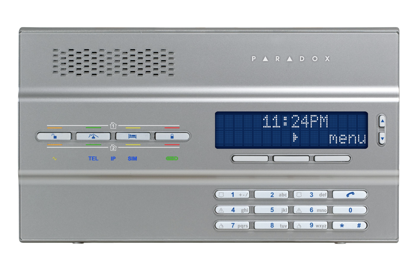 MAGELLAN 2-Partition 64-Zone Wireless Console with GPRS/GSM
I soon found out that the GPRS/GSM part was not included in the system. After a quick search I found the part that I needed:
Without the GPRS/GSM module, I couldn’t know when the alarm was triggered when I wasn’t home. The price was around $150 (not considering the SIM card plan I would have to purchase also).
As a software engineer and a very curious guy, I started thinking of an alternative solution. Since I can remember, I have always wanted to know how things work, why is this bug really happening, or what makes this device work. But when it comes to electronics, I know nothing (Jon Snow :)) or even -1 in some cases.
My first thought was: what if I could use an Arduino (or a similar device) to detect when the electric signal is sent to the alarm bell, and send an HTTP request somewhere so that I can get notified on my phone?
I started googling and come across with the ESP8266 NodeMCU almost immediately:
This is just like an Arduino, but with a WIFI chip included, much smaller, and only $6. Using the ESP8266 and the voltage sensor below, I should be able to do get somewhere…
Just when I was about to do a small test, I opened the console and noticed a port labeled SERIAL.
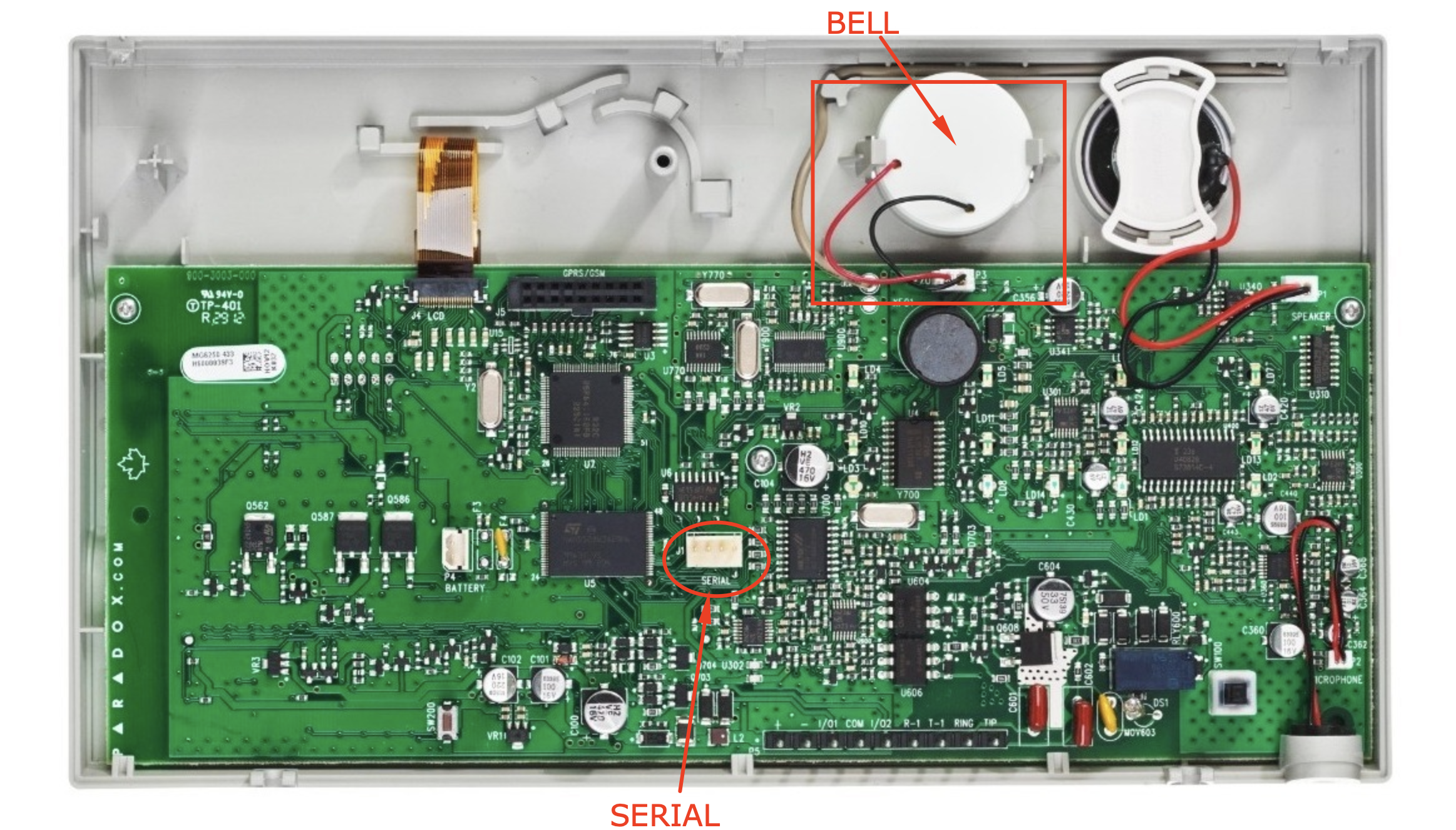
I started investigating what I could do using the serial port. Along the way, I burned an ESP8266, most probably because the serial port outputs around 4V when the NodeMCU board expects 3.3V on the TX/RX pins. This is just a guess. I’m not exactly sure how this happened, but I wasn’t able to upload anything to the microcontroller anymore.
I ended up buying another ESP8266 NodeMCU board. I didn’t notice that the new board was much bigger than the previous. It did not even fit in a standard breadboard… I had to use two breadboards.
To start, I already knew that the baudrate for the MG6250 was 57600. There is also software and hardware made by Paradox for communicating and managing the console. The connector image below interfaces with the serial port directly. So, I suspected that I could get some information using the serial port as well.
Meanwhile, I discovered a lot of projects on the internet, specifically on GitHub, that already interfaced with other Paradox alarms consoles, but not the MG6250 which is a newer system. (e.g ParadoxAlarmInterface (PAI): https://github.com/ParadoxAlarmInterface). More projects down below in the references.
As I progressed with my investigation on the serial port, I discovered a lot of things that might be useful for anyone who wants to communicate with the MG6250 also, and maybe take this experiment to the next level.
Interfacing with the Serial Port
The first real challenge was to figure out the pin layout of the serial port. I had some hints from PAI but, as it turns out, the TX and RX pins were inverted on the MG6250 when compared with the MG5050 (just because):
 MG6250    MG5050
┌───────┐ ┌───────┐
│ Tx   ┌╵ │ Rx   ┌╵
│ Rx   │  │ Tx   │
│ GND  │  │ GND  │
│ AUX+ └╷ │ AUX+ └╷
└───────┘ └───────┘
Once I managed to connect the serial port to the Arduino (yes.. I also bought an Arduino Uno because it is 5V tolerant on the GPIO pins), I started receiving a lot of garbage on the serial monitor. However, this garbage only appeared when some event was triggered (e.g. like a motion sensor). Hence, I was on the right track, however, assuming the baudrate was correct, I assumed that the messages could be encrypted. Digging in on the PAI code, I could see some user/passwords being sent to the alarm console. I tried a couple of things without any luck. I was beginning to lose hope when I discovered the first breakthrough in one of the MG6250 manuals (MG6250 Section Programming Guide):
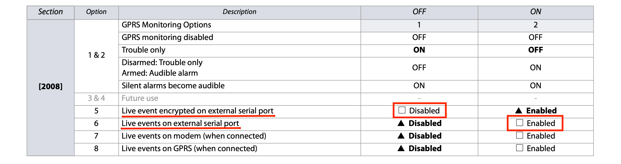
As it turns out, I could just configure the alarm console to start sending live unencrypted events over the serial port. Switching the settings above, I started receiving more readable messages. I could even see the sensor location names configured by the installer (e.g. OFFICE, KITCHEN, HALL).
Ok, now we are getting somewhere!
Message Protocol
From here on was all about figuring out the protocol used. Easy peasy … or so I thought.
I started by creating a simple python script to do some tests. You can find this script in the GitHub project as well (link at the end).
Following other similar projects for the previous Paradox console models, I was expecting a protocol with a fixed-length message. This was true, at least for some time… I could clearly see that each message was 46 bytes long. I compared different messages to check for patterns. I could already identify some bytes. However, occasionally, the program would crash. As it turns out, the message was not always 46 bytes (of course not… it would be too easy).
There were some messages where the length was bigger than 46 bytes. One of these messages (arming the alarm) was always consistent in length, so I started investigating the pattern for these as well. After much debugging, I figured it out. A message can have multiple events.
The total number of bytes of a given message is actually included in the message, the 4th byte to be exact. Hence, I had to read 4 bytes, check the length, and then read the remaining bytes of the message.
After this step, it was all about parsing the message.
Here is the message layout:
|_ _ _ C _ _ _|_ _ _ _ _ _ _ _ _ _ _ _ _ _ _ _ _ _ _ (...)|_ _|
       7                        37 * E                      2
    ctr bytes                 event bytes             checksum bytes

where C is the message length and E the number of events.
I don’t know the meaning of all the bytes in the message yet, but I know the ones that interest me the most (the event type and sub-type).
Here is the structure that I use for each Event in the message:
struct Event
{
  byte seq;
  byte unknown8;
  byte unknown9;
  byte unknown10;
  byte unknown11;
  byte unknown12;
  byte event;
  byte sub_event;
  byte area;
  byte century;
  byte year;
  byte month;
  byte day;
  byte hour;
  byte minute;
  byte unknown13;
  byte unknown14;
  byte unknown15;
  byte unknown16;
  byte unknown17;
  byte typed;
  char label[17];
};
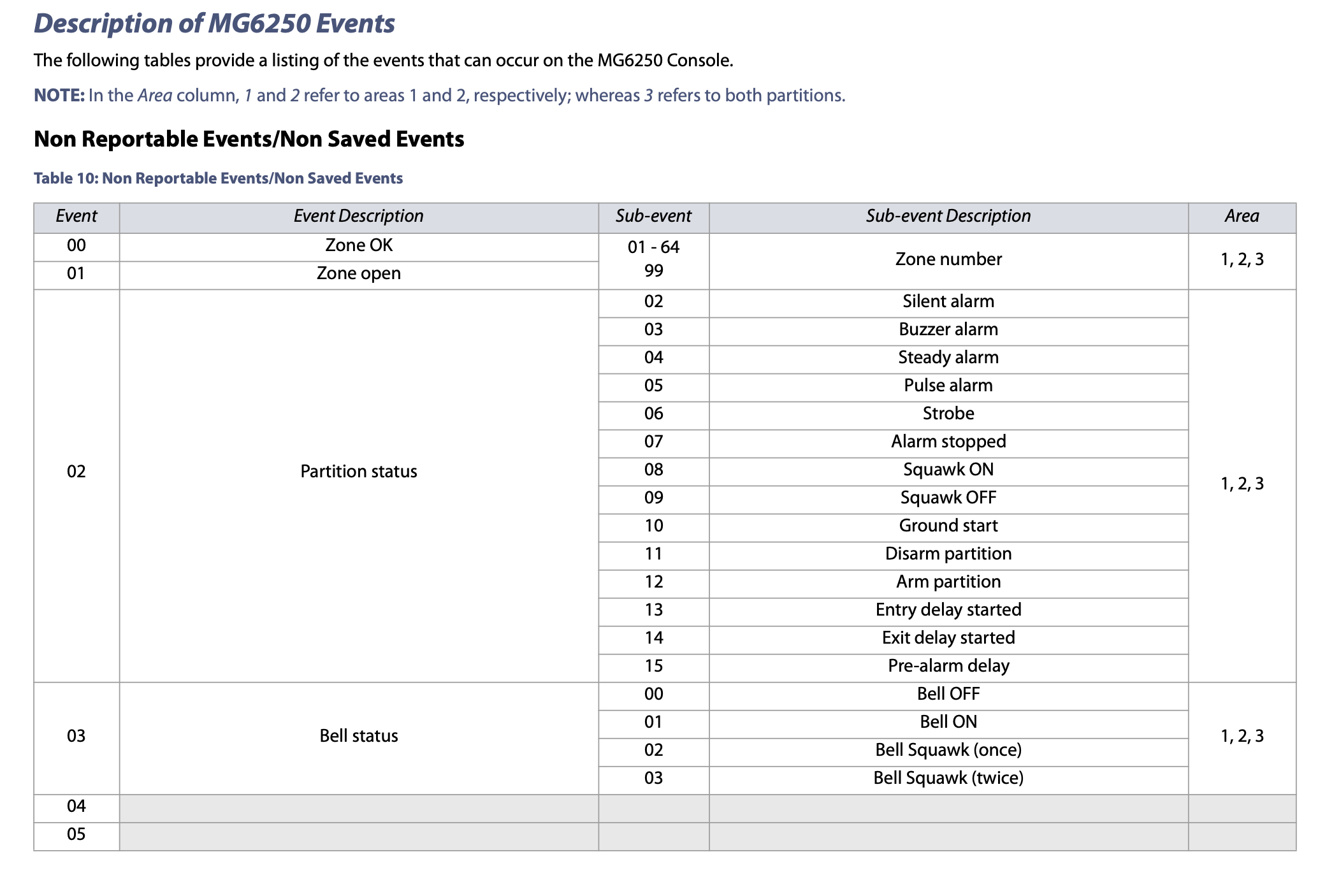
Event decoding
Once again, the MG6250 Section Programming Guide manual helped a lot here. All the event and sub-event codes are described in this manual:
Checksum
After much trial and error, I also managed to figure out the CRC algorithm used for the checksum. The protocol uses the CRC-16/MODBUS. The high order byte is the 46th byte.
V=IR (Ohm’s law)
Once I had the software part figured out, I started working on the circuit. I had only two tasks left to do:
- Power the board (ESP8266 nodeMCU).
- Reduce the voltage on the RX pin from ~4V to 3.3V.
The first task turned out to be very easy. The AUX+ line from the serial port outputs around 7V when the alarm console is connected to the 12V power source.
The second task required me to (re-)learn basic concepts like the ohm’s law to calculate the appropriate resistors for a voltage divider.
Although I had a voltage divider already working in the circuit, I ended up using a voltage regulator: LD1117V33 (datasheet).
Reporting alarm events to MQTT and Home Assistant
From here on, it was all about connecting the dots. Using the ESP8266 to connect to my WIFI network and sending the appropriate events to an MQTT broker installed on my Home Assistant server. Of course, once again, I had to by a Raspberry PI 4 with an A2 microSD card and the appropriate USC-C charger, to run Home Assistant.
Home Assistant provides an app for both iOS and Android devices. Any message received by the MQTT broker can be automated into a notification on my phone. And that’s what I did.
I created a C++ sketch, which I uploaded and tested via Arduino IDE. This sketch listens to messages on the RX pin from the MG6250 console and reports the appropriate events to the MQTT broker. You can find this sketch on the GitHub project below.
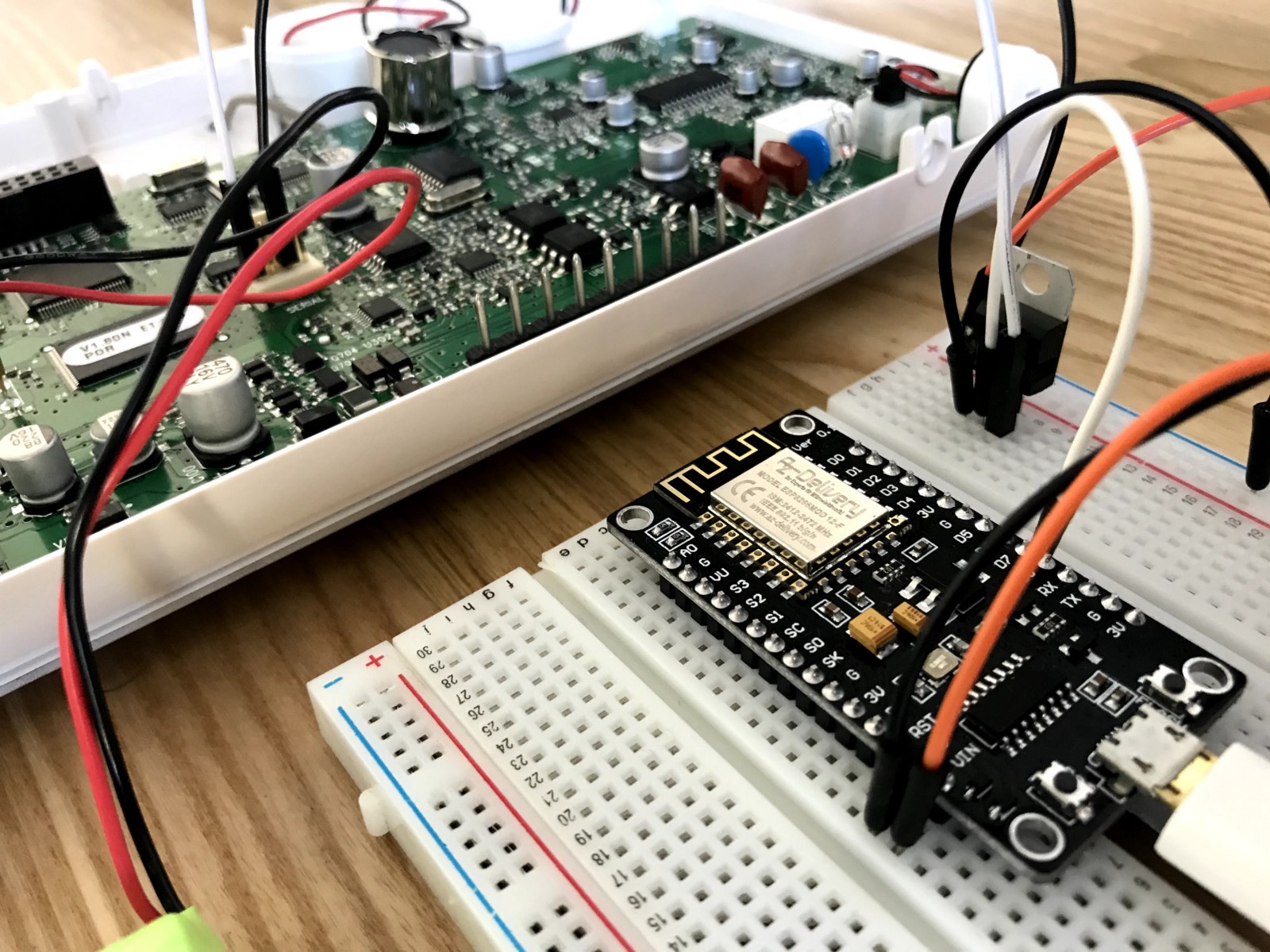
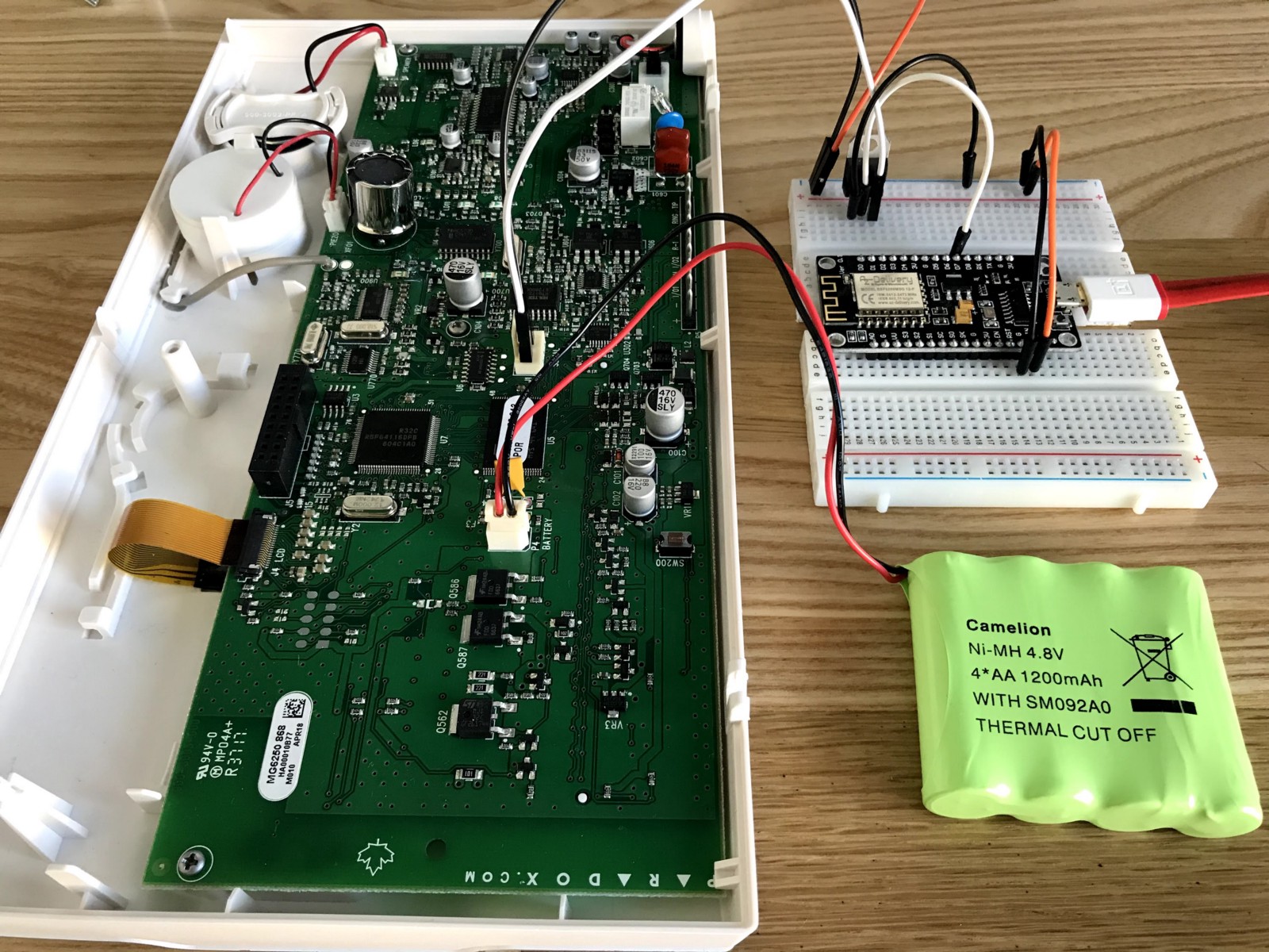
Here are some photos of the circuit while I was debugging the messages.
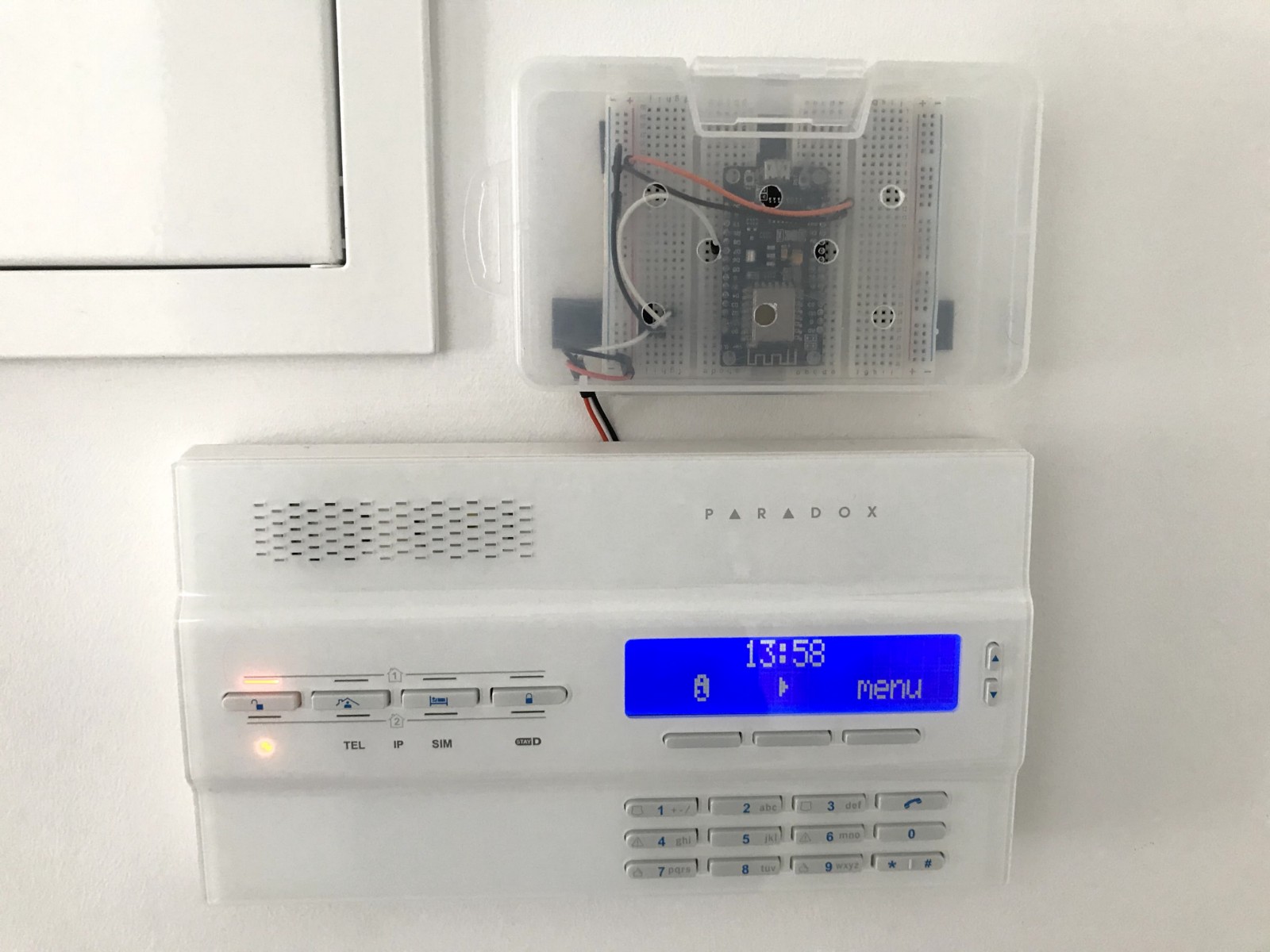
… and here is the project in “production”. Very professional, do you agree? (of course not).
What about controlling the Alarm?
Well, this is the tricky part. Although there are some examples in similar projects targeting other Paradox alarm models (MG5050), I was not able to send successful messages to the MG6250 console. :(
I’m missing some essential tools in order to reverse engineer this part as well. I would need examples of valid messages sent to the console. Listening to messages sent by the Babyware software (by Paradox) could be a solution. Once I know the protocol for sending messages, I can use the MG6250 section programming manual to send the appropriate events to arm or disarm the alarm. For this, I would need the Babyware software, and probably the 307USB connector (picture above).
What’s next?
The obvious improvement is to be able to communicate with the alarm console so that I can arm the alarm when I’m not home, or even have some automation for this in Home Assistant.
Another possible improvement is related to the battery performance of the sketch. Right now, I’m not using any deep sleep mode, resulting in the worst performance as the board is always running.
I think deep sleep is difficult (if not impossible) to achieve because the board needs to awake when an RX signal arrives. Although I haven’t tested this yet, I suspect the time the board takes to wake up and boot, would result in losing bytes from the serial message.
Final thoughts
Debugging this project was very fun. You can really combine programming with exercise as, in order to receive events from the console, I would often have to get up, walk in front of a motion detector sensor and sit down again to see the result. Triggering the alarm bell on purpose, scaring the neighborhood, was fun too. I had to see what were the events sent by the console when the alarm was triggered, of course.
I ended up spending a lot more money than the price of the GPRS/GSM module, but the things I learned along the way, have no price!
GitHub project
You can find the sketch for this project below. There is also a Python script that I used to investigate the protocol connecting the console serial port direclty to a PC.
mg6250_mqtt - https://github.com/bmpc/mg6250_mqtt
References